DCF77 OLED-clock
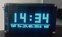
This time, a small project that requires no own layout or circuit design - so perfect in between for something to tinkering and programming.
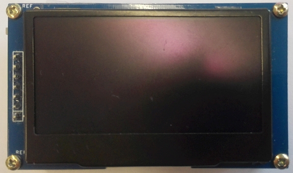
Inspired by the web sites have built a pong-clock, the idea came to build a small DCF77 clock with multiple modes - even Pong - supported and uses an active display for easy reading in the dark. Since LCD displays always produce a shimmer around the display with the backlight, the choice fell on an OLED display with 128 x 64 pixels. Such displays can be found online with 2.42" at reasonable prices.
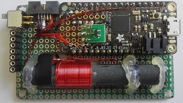
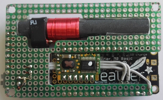
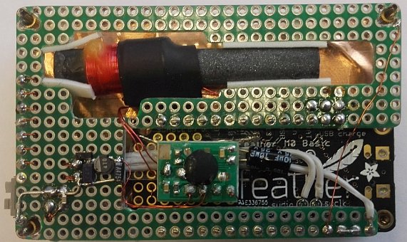
As controller, a Adafruit Feather M0 Basic with the Atmel SAMD21 Cortex-M0 and a JST-PH connector for a LiPo battery is used. Thus, the clock can run for some time without power supply continue and the battery is automatically charged when plugged in. On the free surface of the Feather M0 Basic the DCF-receiver is soldered.
The USB power supply, the planned HKW-module and the proximity of the antenna to the display were doing a real challenge ...
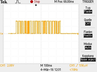
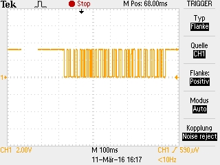
The order of the DCF77 receiver module and antenna from HKW provides on its internet store is not a problem. The relatively high price is made up for by the complete signal preprocessing. Only the full document is not sent and is not (any longer) on the side of the company to find. Some search the web at least brought out some posts and an older version.
To connect the output of the HKW-receiver directly to the input of a MCU UART, the signal must be inverted. For his I have used a MOSFET transistor with a resistor.
Unfortunately, the HKW-module stops working after three days and passed into the collection of paperweights and the re-ordered two new modules have unfortunately never delivered an output ... Upon reflection and searching the web, I switched to the DCF-receiver DCF1 of Pollin. He is considered as not particularly stable signal, but appears not to be a sensitive soul. But one this module a good signal filters and an excellent Vcc filters is required to elicit to him a usable datagrams. Furthermore, the OLED display includes a DC/DC converter and he interference with the receiver. So the display requires a shielding. This is made of self-adhesive copper foil for guitars and placed over the display unit. This large ground area between the display and DCF antenna brings however again a significant deterioration of the reception quality...
Since the Adafruit Feather M0 runs with a 32.768 kHz RTC oscillator as a base, the software can continue to count the time itself. Only the date I have left the DCF receiver to recognize the lack of DCF Sync clearly. And after several weeks, I can say that only to weather-related adverse days, the date was not correct in the morning. However, the antenna must be well aligned to Frankfurt/Main...
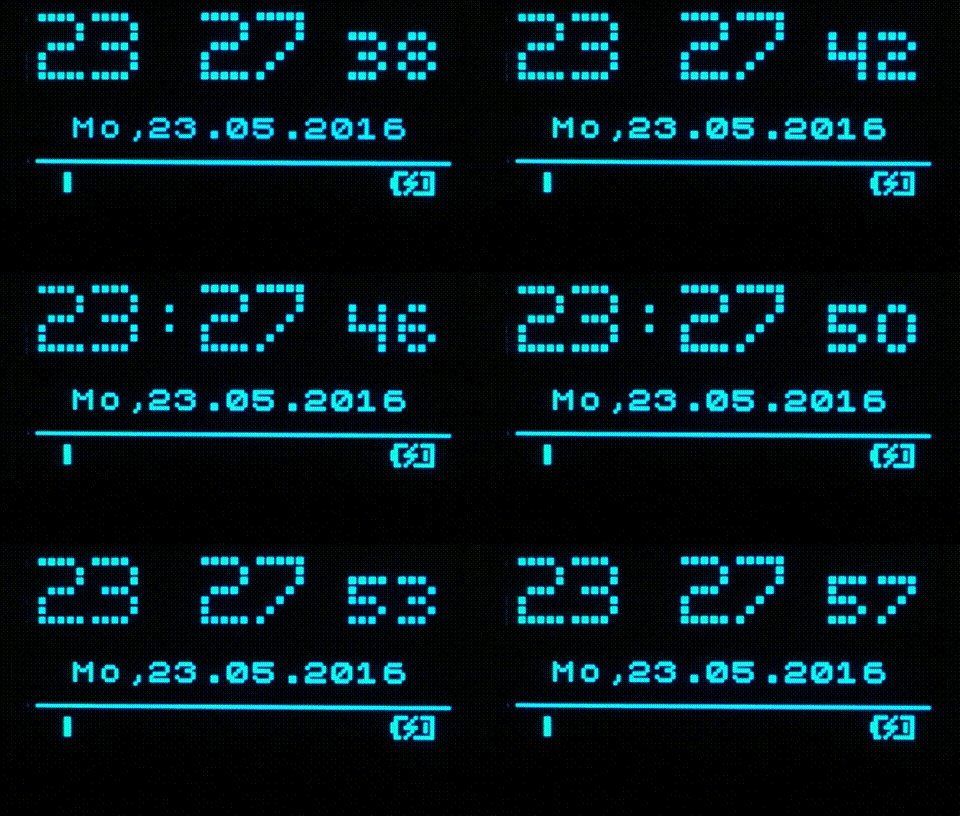
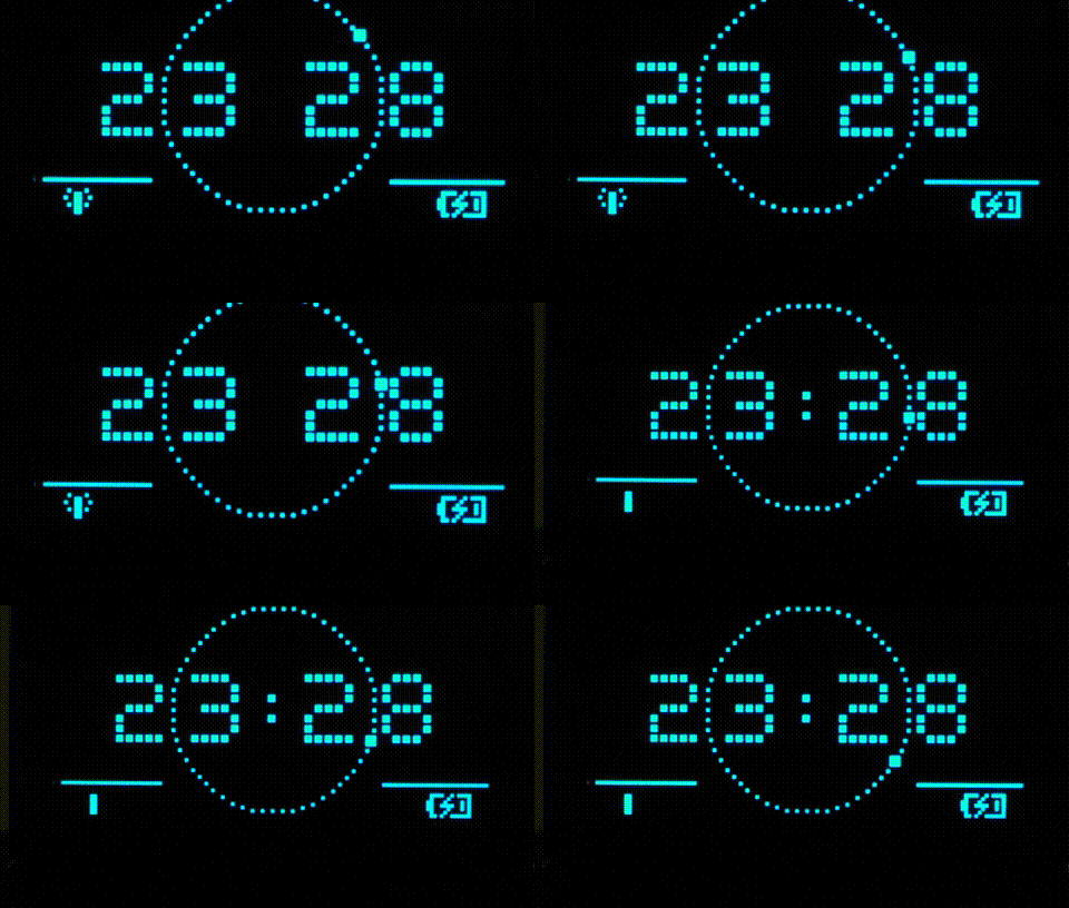
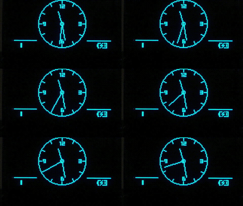
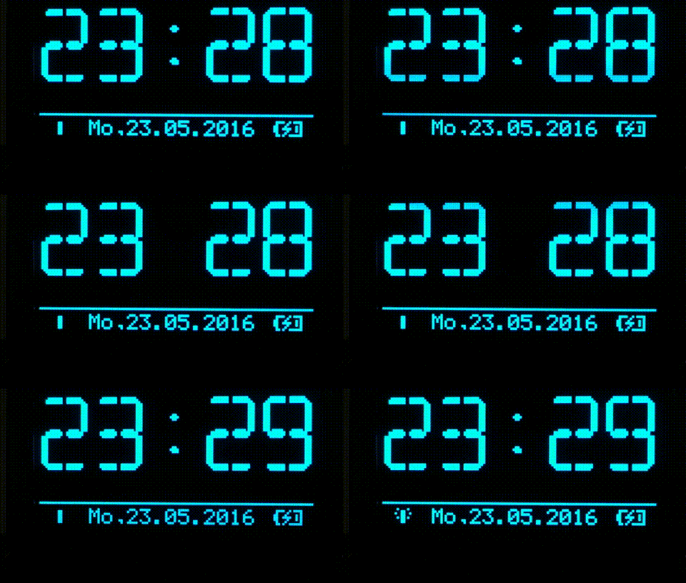
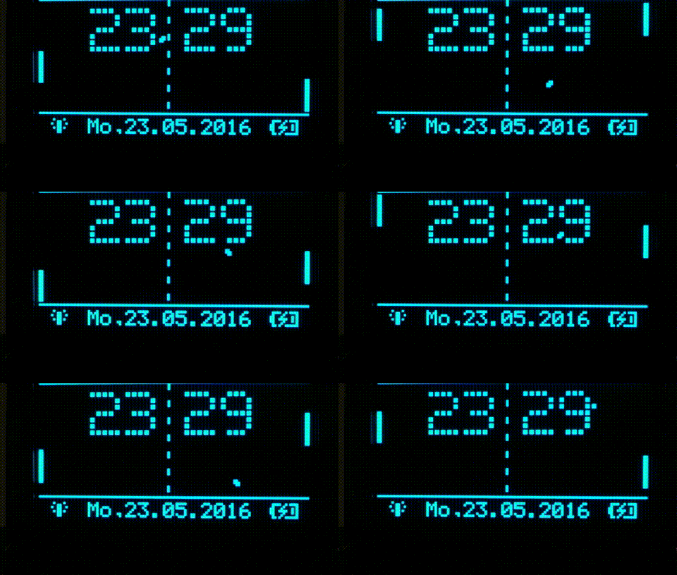
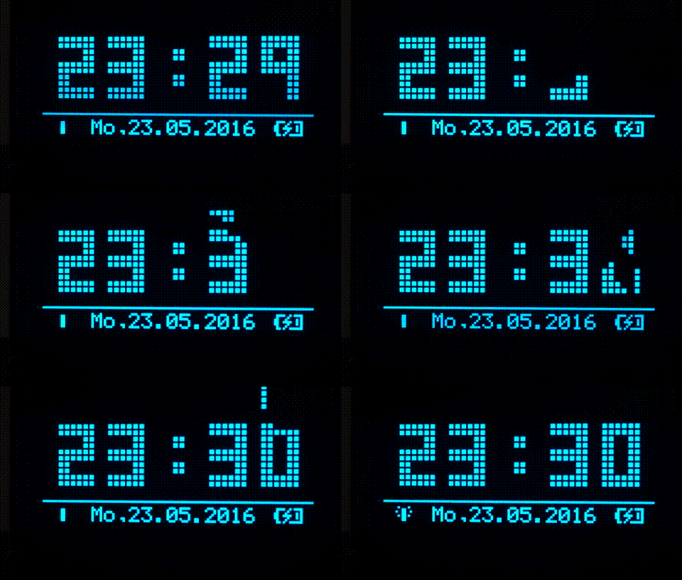
So I have implemented the following modes. The best as "analog", "pong" and "tetris" are not rewritten by me. The reference to the org. Authors are documented in the specific source code.
And here is the complete source code along with the Keil-project of the DCF_OLED-clock.
![]()
DCF_OLED_clock source code & Keil-project (as ZIP)
The icon for the DCF reception is very restrictive handled. Without the minute-mark or after error / parity-error "no sync" is set. As long as the synchronisation is valid - until successful receipt of a complete datagram - "in sync" is used. After successful receipt of a complete error-free datagram "DCF valid" is displayed. Once an error when receiving the subsequent datagram occurs, "no sync" is set again.
Thus a small DCF clock has emerged that supports multiple display modes, runs with USB-power or a LiPo battery with enough space for expansions / improvements. And my son is fascinated by the clock and would best "get hold of" :-)
Open points:
- DCF receive quality
- housing
- A/D reading of the battery state of charge.
No matter what I've tried (sample-num / sample-count) - the value of a real instrument never was determined even approximately.
Below some more good ideas for the clock display:

 deutsch



 About Me
 Contact
 Photos